Keystone Inputs
This section explains the meaning of the dimensions produced by the calculator, and suggests a method for marking out your group on-site based on these dimensions.
Regardless of what type of shape you have chosen you should read the section on the Rectangular Shape Dimensions below is this explains how to mark out the outer border of the shape area.
After reading this section, read the sections on Two Number Dimensions and Custom Shape Dimensions.
Rectangle Shape Dimensions
The rectangle is the simplest shape to map out. The calculator shows you the dimensions of the group, and how far the group is from the camera.
Note the calculator shows the dimensions of the group, NOT the dimensions of the frame area. If you have specified a Border greater than zero then there will be a gap between the edge of the group (as mapped out by these dimensions) and the edge of the image frame.

In the example above the calculator shows that:
- the camera must be 6.9 metres off the ground (the number to the right of the camera symbol)
- the distance from the ground directly below the camera to the centre of the front of the group is 6.5m
- the distance from the centre of the front row to the centre of the back row of the group is 22.6m (giving a total distance from the camera to the back row of 29.1m)
- the total width of the front row is 8.5m, which means the distance from the centre of the front row to the edge of the front row is 4.3m
- the total width of the back row is 26.9m, which means the distance from the centre of the back row to the edge of the back row is 13.4m
Note that measurements are rounded to one decimal place, so totals may differ by 0.1m from the sum on the intermediate lengths. GroupCalc Pro has the option to increase the precision to 2 decimal places (see Settings).
When actually measured out on the ground the outline of the group will look like this:

Below is a suggested method for marking out the group on-site. You will need a method of marking the corners and other important locations, eg: witches hats, pegs, or landscape chalk.
Step 1: Mark the location of the camera
Determine the location of the camera and the direction it will be facing. Mark the location on the ground directly below the camera.
Step 2: Mark the location of the centre of the front row
Measure out the distance from the camera to the centre of the front row (6.5m in this example) and place a marker there.
Step 3: Mark the location of the centre of the back row
Continue walking directly away from the camera long the centre line of the group and measure out the depth of the group, i.e. the distance from the front row of the group to the back row of the group (22.6m in this example).
Place a marker there. This is the centre of the back row of the group.
Step 4: Check that the centre line is straight
Turn and face back towards the camera and sight along the markers you have place. Make sure that the two markers and the camera are in a straight line. If they are not, move one of the markers so that they are in a straight line with the camera. If possible put the camera in the correct location and height, set it to the selected focal length and look through it at the centre line. Make sure that centre line is straight at that the markers for the middle of the front and back row are within the frame.
IF YOUR CENTRE LINE IS WRONG THEN ALL OTHER MEASUREMENTS WILL BE WRONG, SO IT IS IMPORTANT TO TAKE THE TIME TO CHECK!
Step 5: Mark the back corners of the group
Starting at the centre of the back row walk at right angles to the centre line and measure out the distance to the back corner of the group (13.4m in this example). Place a marker there.
Do the same for the opposite back corner of the group.
If possible, put the camera in its correct position and height and look through the camera at the locations of the back corner markers you have just place. Make sure they are square in the frame. If they are not then adjust them so they are evenly placed in the frame.
Step 6: Mark the front corners of the group
Repeat Step 5 with the front corners of the group. In this example the front corners are 4.3m from the centre of the front row.
Step 7: Check you measurements
As a final check put the camera in its correct position and height, with the lens set to the selected focal length. Sight through the camera and ensure that the corners are evenly placed near the corners of the frame. They will not be exactly in the corners of the frame. The gap between the corner markers and the edge of the frame is the gap you defined in the Border setting. If you have set the Border to 0% then the corner markers should be exactly in the corners of the frame.
This section explains the meaning of the Two Numbers Shape dimensions produced by the calculator, and provides step by step instructions for marking out your shape on site based on these dimensions. When marking out the shape on-site you will need something to mark the key positions in the shape, and to mark the lines of the shape. You can use witches hats, pegs, and/or Landscape chalk and string to do this.
To simplify the marking out of the numbers, they are based on digital clock style numbers made up of horizontal and vertical bars. This means that GroupCalc only needs to calculate the widths of these bars, not complex curves. The cross bars are narrower than the vertical bars to allow for the fact that the crossbar will look thicker due to the height of the people in the photos
NOTE: If you don't want to use this square style of numbers then set the shape to Custom then use the Custom Shape Editor to draw the numbers you want (see How to Drawn a Custom Shape)
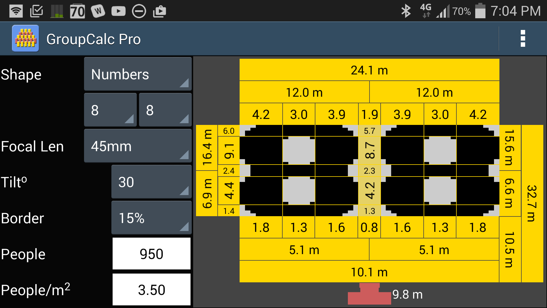
The screen shot above shows the calculated results for a two number shape of "88". As with the Rectangle shape, the dimensions of the outer border of the shape area are shown:
- Width across the front of the shape area - 10.1 metres
- Width across the back of the shape area - 24.1 metres
- The distance from the centre of the front row of the shape to the centre of the group is 6.6m
- The distance from the centre of the back row of the group to the exact centre of the group 15.6
- The sum of these last two figures gives the total depth of the group 15.6m + 6.6m = 22.2m
In addition to the outer dimensions, GroupCalc calculates the width and height of the horizontal bars that make up the number. It also shows the distance between the bars. The widths of the vertical bars will be larger at the back of the group than the front due to keystone distortion. When viewed from the camera these bars will appear to be the same thickness from front to back. Guide lines are included to assisting in marking out the shape onsite.
Below is a step by step explanation of how to use these measurements to mark out the shape on site.
Step 1: Mark out the location of the camera and the outer border of the shape area
See Keystone Results for an explanation of how to mark out the outer border of the shape area, and the location of the camera. The diagram below shows the results of following this procedure for this example.

Step 2: Mark the segment heights along the centre line of the shape area
GroupCalc divides the height of the numbers into the following segments:
- the height of the top, middle, and bottom crossbars of the numbers: 5.7m, 2.3m, and 1.3m respectively in this example
- the height of the gaps between the back and middle crossbars and the middle and front crossbars: 8.7m and 3.8m respectively in this example.
These height measurements are measured at the centre line of the group, not the left or right side.
In this step we mark the height of each these height segment up the centre of the shape as shown in the following diagram.

If you are using GroupCalc Pro, then the heights of the number segments as measured at the edge of the shape are also shown. You can mark these along the edge line of the shape as shown below. This assists in Step 3.
Step 3: Draw the horizontal lines between the height segments
Now that you have mark the boundaries between the height segments, mark a horizontal line through each mark extending to the edges of the shape area...

Step 4: Mark the segment widths at the front and back of the shape
Next you mark the widths of vertical bars and gaps across the front and back of the shape...

Step 5: Mark the "vertical" lines between the width segments
Now that you have marked the boundaries between the width segments, mark a "vertical" line through each mark extending from the marks on front of the shape area to the corresponding marks at the back of the shape area...

Step 6: Use the horizontal and vertical lines as a guide to draw the numbers
Now that you have the guide lines in place you can use them to draw the outline of the numbers...

When viewed through the camera the numbers will look square in the frame.
This section explains the meaning of the Custom Shape dimensions produced by the calculator, and provides step by step instructions for marking out your shape on-site based on these dimensions. When marking out the shape on-site you will need something to mark the key positions in the shape, and to mark the lines of the shape. You can use witches hats, pegs, and/or Landscape chalk and string to do this.
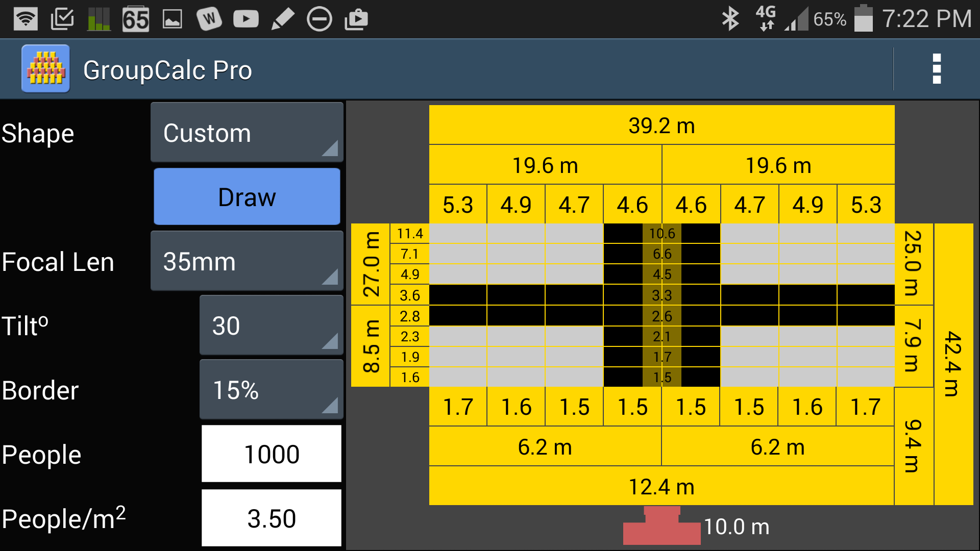
The screen shot above shows the calculated results for a custom shape, in this case a cross. As with the Rectangle shape, the dimensions of the outer border of the shape area are shown:
- Width across the front of the shape area - 12.4 metres
- Width across the back of the shape area - 39.2 metres
- The distance from the centre of the front row of the group to the exact centre of the group is 7.9 metres
- The distance from the exact centre of the group to the centre of the back row of the group is 25.9 metres
- Depth of the shape area measured at the centre line of the shape area is the sum of these last two figures 7.9 + 25.9 = 33.9 metres
In addition to the outer dimensions, GroupCalc divides the width and height of the shape area into eight (8) sections and gives the length of each segment when drawn on-site. When viewed from the camera these segments will appear to be the same size. Guide lines are included to assisting in marking out the shape onsite.
Below is a step by step explanation of how to use these measurements to mark out the shape on-site.
Step 1: Mark out the location of the camera and the outer border of the shape area
See Keystone Results for an explanation of how to mark out the outer border of the shape, and the location of the camera. The diagram below shows the results of following this procedure.
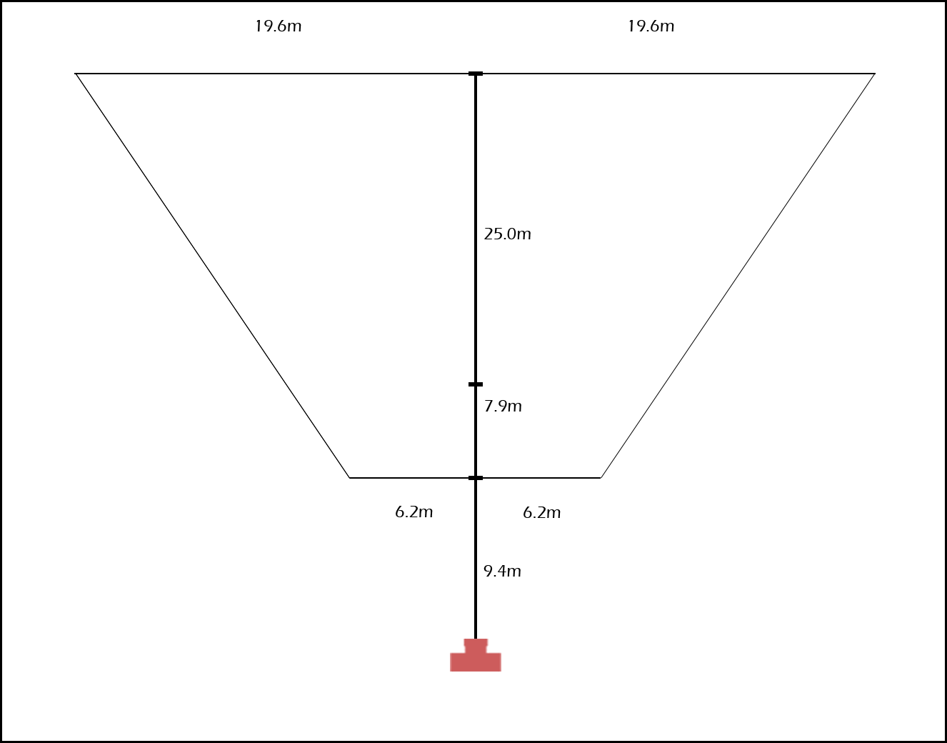
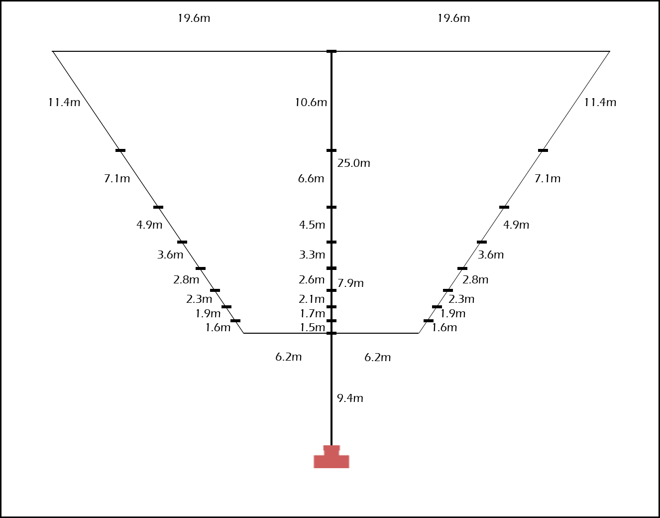
Step 2: Mark the segment heights along the centre line of the shape area
GroupCalc divides the height of the shape area into eight even segment (when viewed from the camera). When marked out on site the height segments get progressively higher towards the back of the shape. The height measurements provided by GroupCalc are measured along the centre line of the shape area, not the left or right side.
In this step we mark the height of each 1/8th height segment up the centre of the shape as shown in the following diagram.
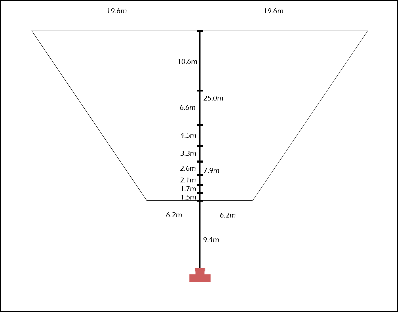
If you are using GroupCalc Pro, then the heights of each eight segment as measured at the edge of the shape are also shown. You can mark these along the edge line of the shape as shown below. This assists in Step 3.
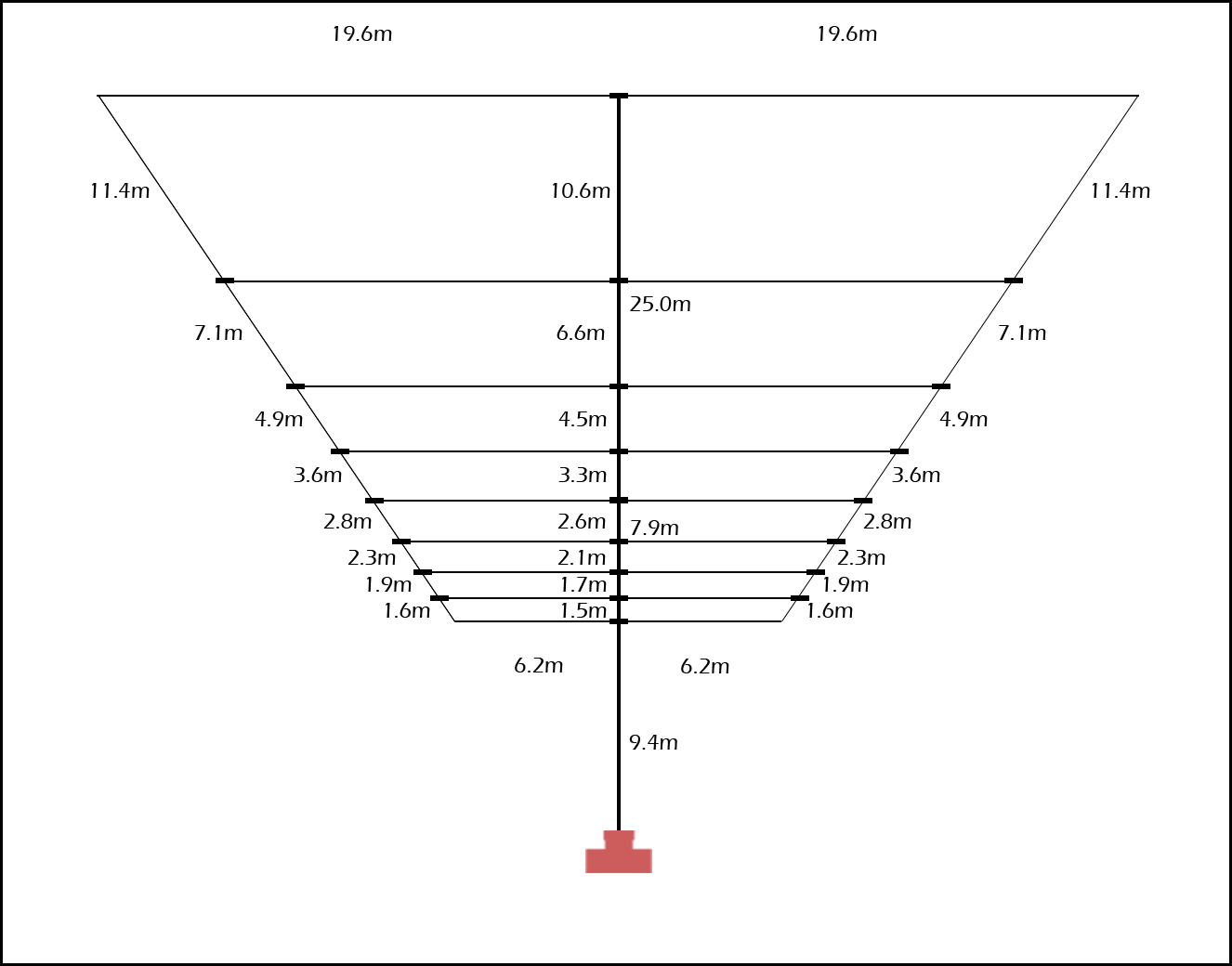
Step 3: Draw the horizontal lines between the eight height segments
Now that you have marked the boundaries between the height segments, mark a horizontal line through each mark extending to the edges of the shape area...
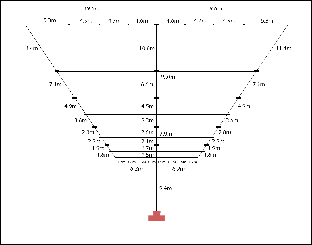
Step 4: Mark the segment widths at the front and back of the shape
Next you mark the widths of each of the 1/8 width segments across the front and back of the shape...
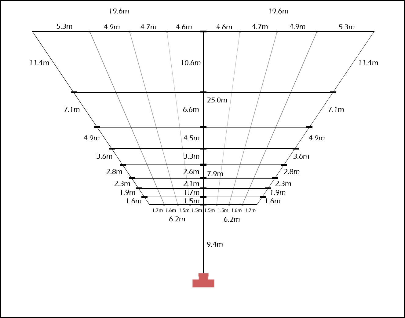
Step 5: Mark the "vertical" lines between the width segments
Now that you have marked the boundaries between the width segments, mark a "vertical" line through each mark extending from the marks on front of the shape area to the correstponding marks at the back of the shape area...
Step 6: Use the horizontal and vertical lines as a guide to draw your shape
Now that you have the guide lines in place you can use them to draw the outline of your shape...
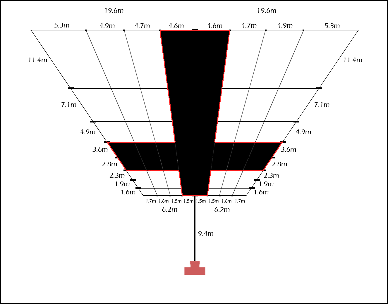
When viewed through the camera you shape will look square in the frame.

